
Revit logic (and walls that don’t show as cut)
Revit Logic:
At the start of Revit training there are a few fundamental things that I get out of the way with trainees that I think need to be addressed. One of these point is to do with “Revit logic” as I like to call it and it is do with the assumptions that Revit makes behind the scenes to show elements certain ways in our views.
Let me give a few examples to explain where I going with this. I’ve been asked numerous times about why Revit doesn’t show materials of stairs when a Plan view is set to “realistic”. The “Revit logic” is that the architectural convention is to show stairs as a semi-symbolic element that shows the overall size, the treads and railings but makes to attempt to represent the stair in great detail. We might look at Plan views of elements all the time and there are numerous conventions about the way that things are shown that we may not even question or have consciously thought about. (BTW the solution to the Stair conundrum is to use a 3D axonometric view that is set to match a Plan view……)
Another example is that that a component family will show as if it is being cut in Plan view if is set to “casework” and yet the exact same object will show as if it is being looked at from above regardless of where it is cut if it is set to “Furniture”. That’s Revit logic – and again it’s got to do with the way that working drawings have been created since goodness knows when – you don’t expect to see the top of your fancy high back executive chairs being sliced through in a Plan right?
The other disciplines such as mechanical (HVAC) and Structural all have their unique way of displaying items and if we switch a view discipline from one to another, the way that the same elements displays alters drastically. Revit will show all ducting in a view above or below the cut plane. Structural elements display as line elements (no geometry) when the display is set to a coarse detail level. This is all part of the logic inside the software and it reflects the way that these disciplines represent objects.
So the way things look and interact is all built on a series of logical decisions made during the development of the software. That is to say, regardless of whether I agree with the way something looks or interacts, I can at least know that this behaviour was the result of consideration on behalf of the developers. By realising this we can start to think the way Revit thinks (whether we agree with the logic or not) and stop fighting battles we can’t win so that we can spend time more productively.
OK, so that’s a long build up to the topic of this post but I think it bears saying and it is a valuable lesson. Plus it nicely explains the reason behind the “issue” that I am about to discuss.
Revit Walls not showing as cut in a Plan View.
Every once in a while we get contacted in support to offer advice about why certain walls in a Plan view don’t look right as they are being sliced through by the Cut Plane of the view yet they show as being “in projection” i.e. not cut. There is a logical (Revit logic!) reason why this happens. Again, you may not agree with logic but knowing the reasoning will assist in finding a solution.
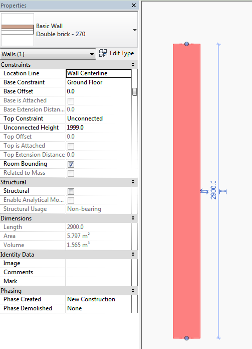
The developers decided that any wall that was set to unconnected (i.e. not constrained to a level) and which did not attach to a Roof above and which was below 2000mm (in the Metric versions of Revit) is to be considered a “low” wall and therefore it will not show as cut. That’s inescapable Revit logic right there and although it only applies to a certain set of circumstances, it might occur in one of your projects. So knowing this we just need to look for a solution. Interestingly, if I make the wall lower than 2000mm but higher than the cut-plane initially it will display as cut but if I lower the wall to below the cutplane then make higher again (but below 2000mm) if will remain showing as if not cut. Deep logic at work?
This screen-cap shows the selected wall which is set to unconstrained – 1999mm high and which is showing as uncut:
So knowing all this, what do we do to get around this?
There are a few solutions. The first one involves altering the base offset of the Walls and then changing the cut plane by using a Plan Region over the affected walls. I don’t like this as it is an inelegant solution.
The 2nd solution is to simply constrain the top of the wall to a level then give it the necessary offset from that level. Revit will now display the wall as cut and if you’ve used the offset from level or join top command correctly then they will be correct in the 3D model too. So this solution satisfies Revit’s inbuilt logic (which you can’t escape) and gets you the result you want without too much drama – simply as a result of knowing what Revit is thinking.
This screencap is the same wall as above which is constrained to the Level above then given a high offset –
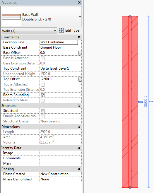
Revit’s logic is now satisfied and the wall can be effectively the same height but it now shows the way you want.
I hope that helps to shed some light on this specific scenario but also opens up a wider discussion about Revit logic and how we can recognise it and work it, not against it. So as always, have fun!
